If you’re in the market for sheet metal parts, you already know that distortion isn’t just a minor nuisance—it’s a costly headache. As a sheet metal fabrication parts supplier with over a decade of serving industries ranging from aerospace to consumer electronics, I’ve seen first-hand how a single warped bracket or misaligned panel can derail production timelines, waste materials, and even compromise end-product performance. Distortion happens at every step of the fabrication process: cutting, bending, welding, finishing, and even handling between operations. The good news is that most cases are preventable with intentional, science-backed practices. Below, I’ll break down the root causes of distortion and the actionable steps we implement at our shop to deliver consistently straight, accurate sheet metal parts for our clients. Sheet Metal Fabrication Parts
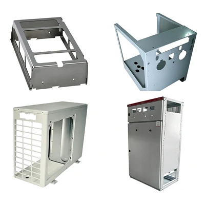
Let’s start with the basics: what causes distortion in sheet metal, anyway? It boils down to uneven thermal or mechanical stress that exceeds the material’s yield strength, leading to permanent, unwanted shape change. When you bend a sheet, for example, the outer edge stretches and the inner edge compresses—if that stress isn’t balanced, the part will spring back or twist after the bend. With welding, it’s even more straightforward: localized heating during the weld creates thermal expansion, and when the metal cools, it contracts unevenly, pulling adjacent areas out of shape. Even something as simple as a poorly secured sheet during laser cutting can lead to small shifts that cascade into major distortion later. Over the years, we’ve learned that addressing distortion requires looking at the entire fabrication workflow, not just fixing a part after it’s already warped.
First up: material selection and preparation, which are the foundation of distortion control. Not all sheet metal is created equal, and choosing the right material for your application can eliminate most distortion risks before fabrication even starts. For low-stress applications like decorative panels, thinner gauges (16-gauge or lighter) might work fine, but for structural parts—think chassis components or mounting brackets—we always recommend thicker gauges (12-gauge or heavier) or high-tensile materials like HSLA (High-Strength Low-Alloy) steel or aluminum 6061-T6. Thicker metals have higher stiffness, so they’re less prone to bending or twisting under stress during fabrication. That said, even with the right material, poor storage or preparation can introduce stress that leads to distortion. We never leave raw sheet metal stacked flat for weeks at a time; instead, we store it vertically on adjustable racks, which prevents residual stress from gravity-induced warping. Before cutting, we also “condition” flat sheets by running them through a stress-relieving leveling machine to eliminate any internal stresses that accumulated during rolling or shipping. This small step has cut our distortion rates for first-time runs by nearly 15%, according to our in-house quality data.
Next, cutting processes: the way we shape the initial sheet has a huge impact on later distortion. Laser cutting, plasma cutting, and shear cutting are the most common methods, but each carries unique distortion risks. Laser cutting is precise, but the intense, localized heat can create a heat-affected zone (HAZ) around the cut edge, which expands and cools faster than the rest of the part—leading to micro-warping. To mitigate this, we program our laser cutters to use nested parts with uniform kerf (material removed per cut) spacing, so heat distribution is even across the sheet. We also avoid making cuts too close to bend lines or existing edges; a general rule of thumb is to leave at least twice the material thickness between a cut and a bend to prevent stress concentration. For shear cutting, which uses a sharp blade to slice metal, distortion happens when the gap between the upper and lower blades is too large, or the blade angle is incorrect. We calibrate our shear machines daily to maintain a gap equal to 5% of the material thickness, which ensures a clean cut with minimal burrs and no shear-induced stress that would cause bending. For parts that will go through multiple cuts, we always sequence cuts to leave the largest possible flat area intact for support during processing—this prevents the part from flexing as it’s cut, which would throw off accuracy.
Bending is another high-risk step for distortion, especially for complex parts with multiple bends. Springback—the tendency of bent metal to return to its original shape after the bend tool is removed—is a common byproduct here, and it’s driven by the same stress imbalance I mentioned earlier. To compensate, we use bend allowances tailored to each material and gauge: for aluminum, springback is about 5-10% of the bend angle, while for steel it’s 2-5%, so we adjust our tooling to overbend slightly to account for this. We also use press brakes with back gauges that are calibrated to within 0.001 inches, so each bend is aligned to the part’s original datum, preventing cumulative angle errors that add up to major distortion. For parts with multiple bends, we always bend them in a sequence that starts with the largest bend angle and moves to the smallest, or from the center of the part outward. This way, each new bend doesn’t disrupt the stress of already formed features. For example, when bending a U-channel, we bend the two end flanges first, then the center—doing the opposite would cause the flanges to twist as the center bend is formed. We also never bend a part that’s been previously cut and left unsupported; we clamp it to a custom fixture during bending to hold its shape, which is critical for thin gauges that are prone to flexing.
Welding is where a lot of customers run into unexpected distortion, especially if they’re sourcing from suppliers that skip proper welding techniques. The problem is thermal contraction: when you melt a weld, the surrounding metal heats up and expands, but as it cools, it shrinks. If that shrinkage isn’t controlled, it can pull a part out of alignment, warp edges, or create gaps between joined components. The first rule we follow is to use the smallest possible weld that meets strength requirements—avoiding oversized weld beads that add unnecessary heat to the area. For MIG welding on steel, we use pulsed MIG instead of standard MIG, which delivers shorter, more controlled heat pulses that minimize thermal spread. For aluminum, which is far more susceptible to heat distortion than steel, we use TIG welding with argon shielding gas and keep the amperage as low as possible. We also implement “staggered” welding sequences, where we weld short sections of a joint, alternating sides, instead of welding the entire joint in one pass. This allows each weld section to cool evenly, rather than building up heat in one area. For larger assemblies, we use modular welding: weld smaller sub-assemblies first, then join them together, so any distortion in the sub-assemblies is fixed before adding more components. We also use post-weld stress relief: for critical parts, we bake them in an oven at 300-400 degrees Fahrenheit for 2-3 hours, which reduces residual stress by up to 80% and eliminates any minor warping from welding.
Finishing and handling are the final steps that can introduce distortion, and they’re often overlooked. Powder coating, a common finish for sheet metal parts, involves applying electrostatic powder and curing it in an oven at 350-400 degrees Fahrenheit for 10-15 minutes. That high heat can cause thin-gauge parts to warp if they’re not supported properly in the oven. We use custom oven racks with divots and clamps to hold parts flat during curing, and for parts thinner than 18-gauge, we add a temporary support bracket (made of low-carbon steel) that we remove after finishing. Even handling between operations can cause distortion: dragging a part across a workbench, lifting it by a single edge, or stacking heavy parts on top of each other can bend thin sections. At our shop, every part is handled with rubber-tipped tongs to avoid scratching and flexing, and we store finished parts in labeled, vertical bins so they don’t get crushed. We also inspect every part at three checkpoints: after cutting, after bending, and after finishing. Our quality team uses coordinate measuring machines (CMMs) for high-precision parts, and digital calipers for smaller runs, to catch any distortion before it ships to the customer.
I know this sounds like a lot of steps, and I get it—if you’re not a sheet metal fabrication expert, it can be hard to know which controls matter most for your specific parts. That’s why, as a supplier, we work closely with every customer to tailor our processes to their needs. If you’re building aerospace components, we’ll prioritize stress relief and precision bending. If you’re making consumer electronics enclosures, we’ll focus on laser cut accuracy and powder coating support to avoid warping. We also offer prototyping services, so you can test a small run of parts and catch any distortion issues early, before committing to a full production order. A common mistake customers make is skipping prototyping to save time, only to find that their full production run has a 20% distortion rate—costing them thousands in rework and delays. We always encourage prototyping because it lets us adjust our techniques before scaling up.
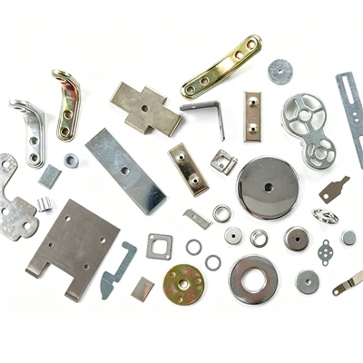
If you’ve been struggling with distorted sheet metal parts from your current supplier, or you’re looking for a partner that prioritizes precision over speed, we’re here to help. Our team of fabricators, engineers, and quality specialists has decades of experience solving distortion-related problems for clients across industries, and we’ll work with you to design a fabrication process that delivers parts that meet your exact specs, on time and on budget. We’re currently accepting new projects for 2024, from low-volume prototypes to high-volume production runs, and we’d love to discuss your needs, walk you through our quality control process, and show you examples of distortion-free parts we’ve delivered to past clients.
Sheet Metal Fabrication Parts To support the science behind these practices, I’ve compiled a list of key resources that we rely on at our shop:
- "Metal Fabrication: Principles and Practice" by John G. Nee, Wiley
- "Distortion Control in Welded Structures" by T. H. Northwood, Woodhead Publishing
- "Sheet Metal Forming: Processes and Applications" by Kevan A. Jones, CRC Press
- National Aerospace and Defense Contractors Accreditation Program (NADCAP) Standards for Sheet Metal Fabrication
- American Welding Society (AWS) D1.1 Structural Welding Code – Steel
Jianhu Yuhua Machinery Manufacturing Co., Ltd.
As one of the most professional sheet metal fabrication parts manufacturers and suppliers in China, our products have good reputation in the market. Please rest assured to buy durable sheet metal fabrication parts made in China here from our factory.
Address: No.1 Peiliu South Street, Lugou Town, Jianhu County, Yancheng City, Jiangsu Province, P.R.China
E-mail: 13770213655@163.com
WebSite: https://www.yuhuamfg.com/
